
Bit.HDL Circuit: A Comprehensive Guide
Bit.HDL is a powerful and versatile circuit design tool that has gained significant popularity among engineers and hobbyists alike. Whether you are new to digital design or a seasoned pro, understanding the intricacies of Bit.HDL circuits can greatly enhance your ability to create efficient and reliable digital systems. In this article, we will delve into the various aspects of Bit.HDL circuits, providing you with a comprehensive guide to help you master this remarkable tool.
Understanding Bit.HDL

Bit.HDL is a hardware description language (HDL) that allows users to design and simulate digital circuits. It is widely used in the field of electronic design automation (EDA) and is compatible with a variety of simulation and synthesis tools. By using Bit.HDL, you can create circuits ranging from simple logic gates to complex processors and memory systems.
Getting Started with Bit.HDL
Before diving into the details of Bit.HDL circuits, it is essential to familiarize yourself with the basic syntax and structure of the language. Here are some key points to get you started:
- Variables: Bit.HDL uses variables to store and manipulate data. Variables can be declared with a data type, such as integer, real, or bit.
- Operators: Bit.HDL provides a wide range of operators for performing arithmetic, logical, and relational operations.
- Processes: A process is a block of code that defines the behavior of a circuit. It can contain variables, operators, and other processes.
- Components: Components are reusable building blocks that can be used to create more complex circuits. Bit.HDL provides a library of standard components, such as logic gates, flip-flops, and counters.
Designing Bit.HDL Circuits
Designing a Bit.HDL circuit involves several steps, from defining the requirements to simulating and testing the circuit. Here is a high-level overview of the process:
- Define the requirements: Clearly specify the functionality and performance requirements of your circuit.
- Design the circuit: Use Bit.HDL to create the circuit, incorporating variables, operators, processes, and components as needed.
- Simulate the circuit: Use a simulation tool to test the circuit under various conditions and ensure that it meets the specified requirements.
- Optimize the circuit: Analyze the simulation results and make any necessary adjustments to improve the circuit’s performance.
- Implement the circuit: Once the circuit is optimized, you can use a synthesis tool to generate the corresponding hardware description language (HDL) code for implementation on an FPGA or ASIC.
Bit.HDL Libraries
Bit.HDL comes with a comprehensive library of standard components that can be used to design a wide range of circuits. Here is a brief overview of some of the key libraries available:
| Library | Description |
|---|---|
| Logic | Contains basic logic gates, such as AND, OR, NOT, and XOR. |
| Memory | Provides components for designing memory systems, such as RAM, ROM, and FIFOs. |
| Arithmetic | Includes operators and components for performing arithmetic operations, such as addition, subtraction, and multiplication. |
| Interface | Contains components for interfacing with external devices, such as UART, SPI, and I2C. |
Bit.HDL Simulation
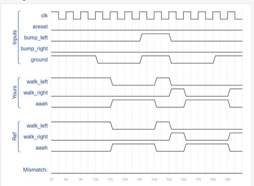
Simulation is a crucial step in the design process, as it allows you to test and verify the functionality of your Bit.HDL circuit. Here are some key points to consider when simulating a Bit.HDL circuit:
- Testbench: A testbench is a separate module that provides input stimuli to the circuit under test. It is essential for


